Are you designing a hydraulic lifting system and want to avoid synchronization issues between cylinders? In this article, we analyze a real case presented to us by a customer, highlighting a specific aspect that is often underestimated by designers: the configuration of the cylinder chamber volumes in a flow divider system.
Let’s see why this can cause cylinder synchronization errors and how to prevent them.
The chosen configuration: master-slave circuit and 2-element MIA-FD
The customer – a company operating in the field of mechanical equipment and lifting machinery manufacturing – was designing a 4-post platform for lifting heavy vehicles using 4 hydraulic cylinders:
- 2 front cylinders: 1A (left) and 1B (right)
- 2 rear cylinders: 2A (left) and 2B (right)
The operating conditions were as follows:
- Approximately 80% of the load on the front cylinders
- Approximately 20% of the load on the rear cylinders
- Around 150 working cycles per day
- The platform had to remain perfectly level at the end of each cycle (ascent and descent)
Absolute precision during movement was not required, but the platform had to remain reasonably level at all times.
2-element MIA-FD
For cylinder control, a 2-element MIA-FD flow divider (Manifold Instantaneous Auto-compensating Flow Divider, model MVA0218), was selected with the following configuration:
- Output 1: left-side cylinders (1A + 2A)
- Output 2: right-side cylinders (1B + 2B)
- Pressure source (hydraulic pump): 2800 psi (~190 atm), constant
The customer chose a Vivoil MIA-FD because it is particularly suitable for this type of application. It can compensate for load differences between actuators and distribute flow to different branches of a circuit with constant and independent flow rates—an essential feature when lifting uneven loads that must remain aligned.
The selected version (MVA – standard divider) does not include a pressure relief valve or a unidirectional flow control for the reunification phase, which are instead available in the MVE version.
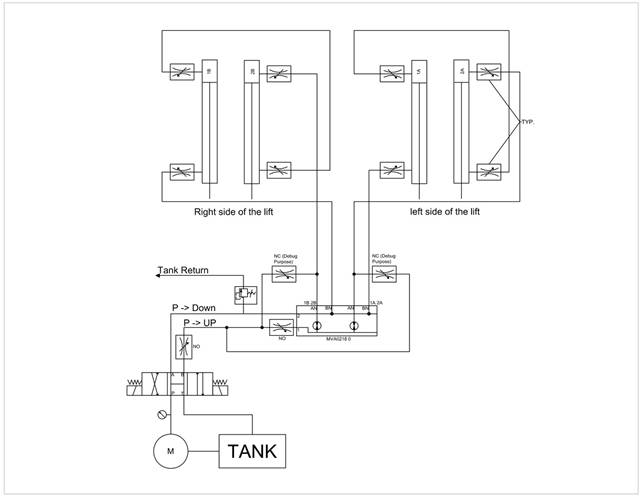
Master-slave circuit
The adopted circuit was of the master-slave type. In this configuration, with a single oil supply, a master cylinder drives a slave cylinder, allowing simultaneous extension and retraction.
In this type of circuit, the hydraulic line is connected to the full-bore side of the master cylinder, whose rod side is connected to the full-bore side of the slave cylinder.
The issue encountered: cylinders not aligning
During prototype testing, the customer observed abnormal behavior: during the descent phase, the front cylinders reached the end of their stroke, while the rear cylinders remained raised by approximately 130 mm. As a result,the platform was not level, despite the hydraulic circuit calculations being considered correct.
At that point, the customer’s doubt did not concern the correct operation of the MIA-FD, but rather the application of this type of flow divider in the master-slave circuit of the machine being designed.
They therefore contacted us to verify whether the problem could depend on the use of the MIA-FD in this configuration.
Vivoil’s analysis: the problem lies in the circuit configuration
After analyzing the design data, we identified the possible cause of the problem: as suspected, it lies in the master-slave configuration, specifically in the volumes of the cylinder chambers.
In fact, for the master-slave system to function correctly, it is necessary that the rod-side volume of the master cylinder is equal to the full-bore side volume of the slave cylinder, and vice versa, as shown in the figure:
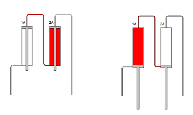
However, when standard cylinders are used, the full-bore side volume is greater than the rod-side volume (due to the presence of the rod).
As a result, when using identical cylinders, it is not possible to obtain a perfect correspondence of volumes and, in some phases of the cycle, the oil cannot completely fill a chamber or cannot fully discharge it.
The result is that one of the cylinders does not complete its stroke and this causes misalignments such as the one observed in the prototype submitted by the customer.
The following two diagrams clearly illustrate the problem :
- Descent: the cylinder cannot fully discharge the oil
If at the beginning of the cycle the full-bore side of cylinder 1 is filled with oil (typical of the descent phase), that oil must flow toward the rod side of cylinder 2. However, the rod-side volume is smaller than the full-bore volume. Therefore, the oil leaving cylinder 1 is greater than the available space in cylinder 2, and part of the oil cannot be completely transferred. Result: cylinder 2 does not complete its stroke and the two cylinders become misaligned.
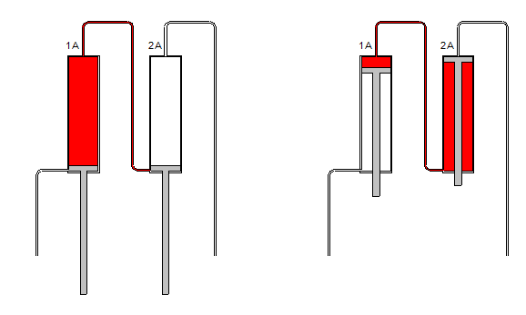
- Ascent: the cylinder cannot fully fill
In the opposite case, at the beginning of the cycle the rod side of cylinder 2 is filled (typical of the ascent phase), and the oil must fill the full-bore side of cylinder 1. However, the full-bore volume is greater than the rod-side volume, and the available oil coming from cylinder 2 is insufficient, so it cannot completely fill the chamber of cylinder 1. Consequently, also in this case, one of the cylinders does not complete its stroke and causes misalignment.
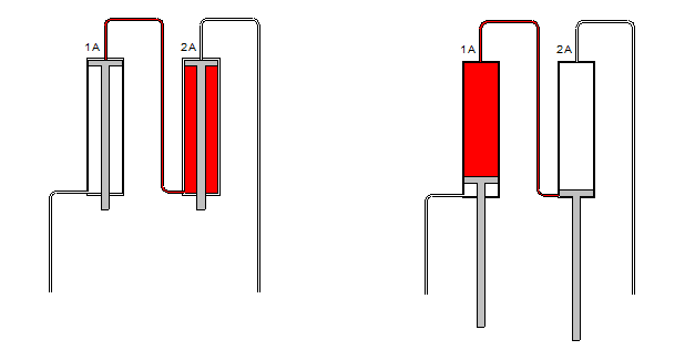
Identical master-slave cylinders before and after an ascent cycle.
The solution: avoid the master-slave system, choose a different configuration and resize the system
To solve the problem, we suggested that the customer eliminate the master-slave system and adopt a different configuration: using 4 independent cylinders controlled by a 4-element MIA-FD flow divider.
In this way, it is no longer necessary to have equivalent volumes between the cylinder chambers, because the Vivoil MIA-FD is capable of distributing constant and independent flow rates and any load differences are automatically compensated.
In fact, the MIA-FD continuously balances the load, ensuring optimal flow division even in the presence of significant imbalances, thanks to its internal gear system and valve compensation that operates instantaneously up to the end of the stroke.
In this way, the platform is able to remain aligned both during ascent and descent, even in the presence of unbalanced loads.
To adopt this solution, however, it is necessary to review the sizing of the hydraulic system, working with a higher flow rate and lower pressure, in order to allow the system to operate correctly with four independent branches.
In lifting systems, it is not enough for calculations to be correct
This case demonstrates that, in lifting systems, it is not sufficient for calculations to be correct. An unsuitable configuration and circuit type can affect the synchronization of the cylinders in a flow divider system.
In this context, the MIA-FD is the most effective solution because, if the system is properly sized, it simplifies control compared to more complex configurations such as the master-slave system.
Are you designing a similar system and want to understand which configuration is most suitable?
Contact us, we will help you identify the best solution for your application.