One of the most frequent questions we receive from our customers is, “How can I calculate the displacement of a Vivoil flow divider knowing only the flow rates?”
In this article we explain which formula to use, and together we look at some examples for calculating the most suitable displacement for your project.
What data are needed and what is the formula for calculating the displacement of a divider?
To calculate the displacement of a flow divider, the flow rate of the individual element must first be calculated.
Do you already have this data? Good!
If you want, you can test the value available to you by following the next steps.
1 – How to calculate the capacity of a single element?
This formula is used to calculate the flow rate of the individual element:
single element flow rate = inlet flow rate/number of elements
Then you need the value of the inlet flow rate (expressed in litres), which is divided by the number of elements in the divider.
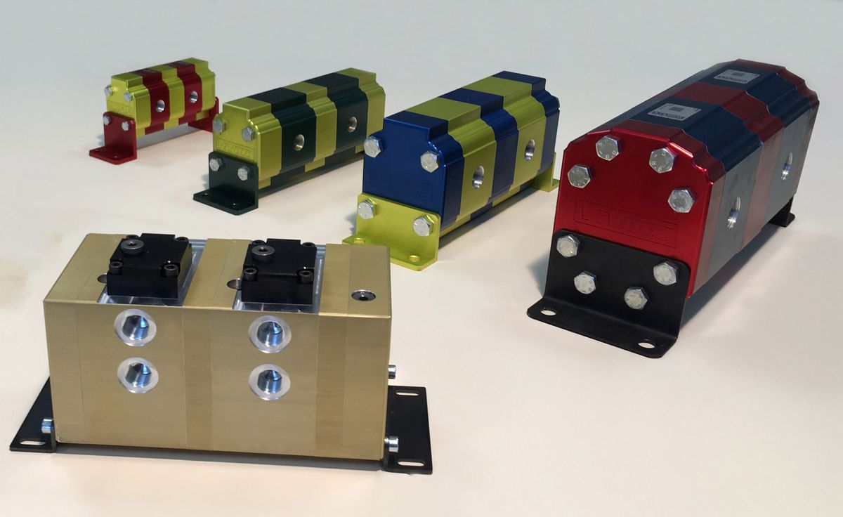
Vivoil flow dividers, for example, are available in different size groups and are modular: some of our models have more than 20 elements! They are complex, high-precision hydraulic components, consisting of a chain of gears that divide the oil into several flows with equal or different ratios.
2 – How to calculate the displacement? Here is the formula and some information
Now that you have the flow rate of the single element, you can quickly estimate the displacement of the flow divider using this formula:
displacement = flow rate of single element/2
Attention! In the calculation you must take into account the flow rate of the individual element expressed in litres.
The value you have obtained allows you to figure out which size group your divider belongs to:
- Group 0 – from 0.17 cc to 2.3 cc
- Group 1 – from 0.9 cc to 9.8 cc
- Group 2 – from 4 cc to 40 cc
- Group 3 – from 15 cc to 90 cc
You might therefore ask yourself: what is the value that allows greater divisor accuracy? Is there a recommended displacement?
The answer is: yes, there is!
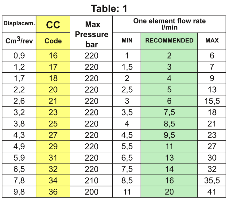
You can find it by comparing the flow rate value per element you have obtained with the table below, which can be found in the catalogue for the identified dimensional group (gr.).
For example for gr. 1 it’s this:
What is the recommended displacement and how to choose the right value?
To help you understand how to choose the most suitable displacement, let’s take a simple example. Let’s assume that the calculation of the flow rate per element gives you a value of 2.5.
In the green column RECOMMENDED of our table, values from 2 to 20 are indicated. In this case you should therefore choose between 2 and 3.
Both displacements are valid, if you are looking for a product that is available from stock at a distributor, both solutions are suitable, especially if you have to stock up.
Generally speaking, however, we recommend that you choose the higher displacement as this will make the divider spin a little slower. In our example, therefore, you should choose 1.2 cc.
A displacement of 2.2 cc would also be fine. These are all valid choices within the given range, but if you drop the rpm, you drop accuracy, noise and absorption. Conversely, if you increase the rpm, you increase accuracy, but also noise and energy consumption.
Calculation of displacement: let’s look at some examples
Example 1 – Let us assume that you have an inlet flow of 30 litres and 3 elements.
The flow rate of the single element in this case is 10 litres = 30/3
While the displacement is equal to: 10 litres/2 so 5.
With 5 cc let’s consider checking the table of gr. 1
Looking at the table we have proposed to you, we see that the value closest to 5 is 4.9 which corresponds to a recommended flow rate of 11.
Example 2 – Let us assume that you have an inlet flow of 60 litres and 3 elements.
The flow rate of the single element is 20 litres = 60 litres /3
While the displacement is 20/2, so 10 cc.
In this case the product is at the limit in gr. 1 and more central in gr. 2, it is then more convenient to select the higher group, especially in the presence of significant working pressures.
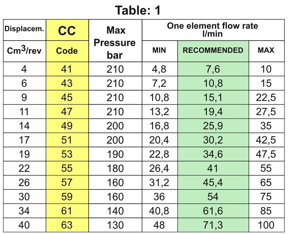
So in this case it is more effective to use the 11 cc gr. 2.
Now that you have the displacement, you may be wondering which type of flow divider is best for your project. Here’s a guide to choosing the right flow divider for your needs.