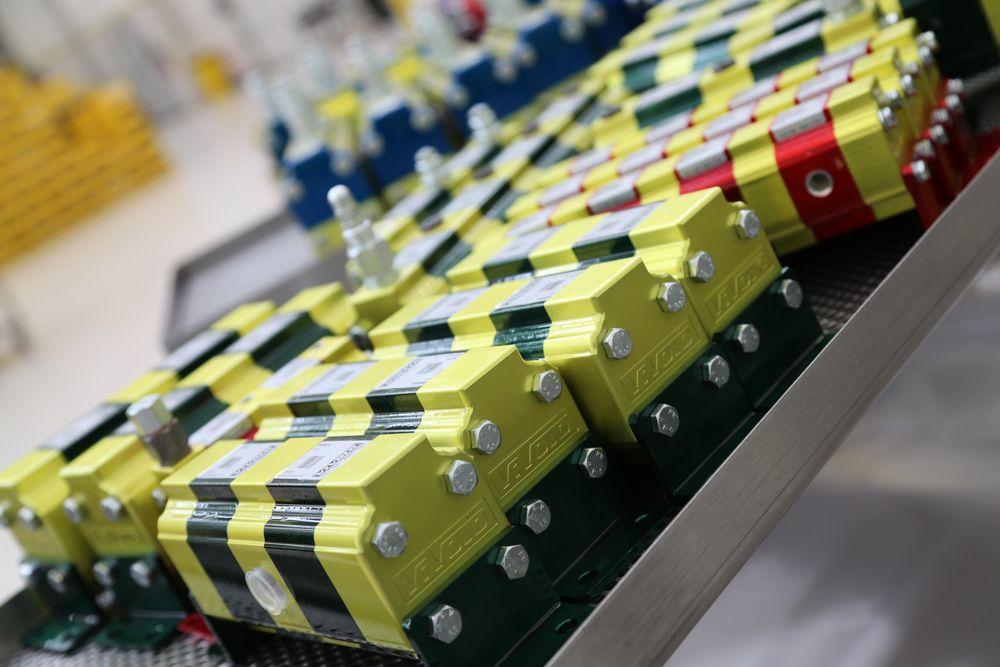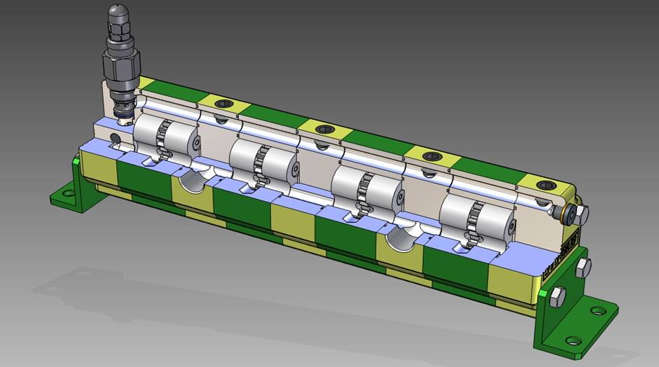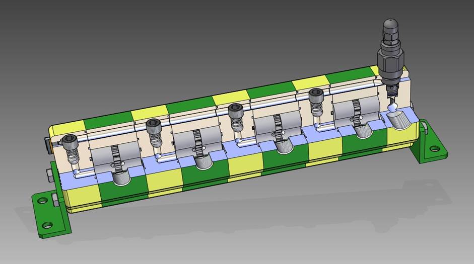
Hydraulic flow dividers are very high precision hydraulic components that split the oil into predefined ratio, that could be the same for all the sections or different. This function is due to gears in series, able to divide the inlet oil flow into several flows, with the same or different ratios.
Because of these characteristics, flow dividers can therefore be used for 3 main functions:
- split the oil flow
- combine the flow, that is to unify the flows
- multiply the pressure
Vivoil hydraulic flow dividers are available in 4 models:
- without valves
- with single re-phasing valve
- with multiple re-phasing and anti-cavitation valves
- MIA-FD self-compensated flow divider
Understanding the different features of each type is the first step to be able to choose the flow divider best suited to your project.
1 – Flow dividers without valves
The dividers without valves can be used for all three mentioned functions, as: divide the flow, combine the flow and multiply the pressure.
We suggest this choice if the application has not high movement frequencies (few cycles).
2 – Flow dividers with single re-phasing valve
Single-valve dividers too can be used to divide or combine the flow and multiply the pressure but, unlike those with multiple valves, they are easier to set. In fact it is enough adjust the pressure of the only valve present in the component to set all the elements. With this type of divider, the error is resetted to zero at each stroke end in a single direction only.
3 – Flow dividers with multiple re-phasing and anti-cavitation valves
Unlike the model we have just seen, this type of divider has both relief valve and anti-cavitation valve in each section, and that the error is resetted in both directions.
It’ s suitable for all the three typical functions of the flow divider.
4 – MIA-FD self-compensated flow divider
MIA-FD, acronymus of Manifold Instantaneous Auto-compensated Flow Divider, is our new generation of dividers. It has been designed it to split and feed the different sections with constant and independent flow rates.
It is an innovative product because, in addition to the normal gear division system, it is pressure compensated, so to allow managing the different loads on cylinders while keeping the very best division, even in conditions of great pressure differences.
Unlike the other dividers we produce, the MIA-FD cannot be used as a pressure multiplier.
It is currently available only for group 1 and is characterized by the continuous realignment of the flow rates. As a result the error is continuously cleared.
Moreover it is pre-arranged with CETOP 3 flanges that allow fitting of 2 either 3 postions valves to customize its functionality. So it is not only a compensated flow divider, but also a real manifold.
How to choose the most suitable model for you in 3 steps
To choose the hydraulic flow divider that best suits your project, all you have to do is follow the next 3 steps.
1 – Decide which capacity you want to divide and then define the displacement
To choose the flow divider best suited for your project, you must first define the displacement of each single section by using this formula:
capacity of the single element = total inlet flow / number of sections
and then define the displacement with this easy calculation:
displacement = capacity of the single section / 2000
Or better, you can identify the displacement you need by using the tables in our technical catalogues, taking care of the suggested flow rate showed there.
2 – Choose the group size
Now that you know which displacement you need, check that it is compatible with the pressure you want to achieve and identify the most suitable group size.
Our flow dividers are available in four group sizes:
- group 0: displacement 0.16 cm3 / rev – 2.28 cm3 / rev, maximum pressure up to 210 bar
- group 1: displacement 0.91 cm3 / rev – 9.88 cm3 / rev, maximum pressure up to 220 bar.
For the MIA-FD flow divider the maximum pressure is 250 bar. - group 2: displacement 4.2 cm3 / rev – 39.6 cm3 / rev, maximum pressure up to 210 bar
- group 3: displacement 14.89 cm3 / rev – 86.87 cm3 / rev, maximum pressure up to 300 bar
In the following table you can see the available Vivoil’ s flow dividers:
| Flow Dividers Model | Group 0 | Group 1 | Group 2 | Group 3 |
| Without valves | X | X | X | X |
| With single re-phasing valve | X | X | ||
| With multiple valves | X | X | X | |
| MIA-FD | X |
Do you need help? Our sales department is here to help.
Contact us, we will be happy to give you a helping hand!
3 – Choose the model for you
The last step is the choice of the model: based on the application you want to get, you can go for a flow divider without valves, or single valve, or multiple valves or the MIA-FD and then define the details with which order it (for example the valve pressure ranges).
Other informations that could be useful to you
Normally the flow dividers have the same displacement, but in some special cases you may need a divider with different flows per section. If so, we can help you choose the best for you.
If instead your project foresees the use with single acting cylinders – when, during the descent, there is no applied load – you could need a special version of the flow divider: the flow divider with motor. In this case in fact the cylinders cannot supply enough pressure to start the gear running and therefore they may not re-enter, but it is enough to connect a gear motor directly to the flow divider to solve the problem.
In some applications it is useful to be able to check the speed of rotation of the gears, to monitoring operations in real time. In this case, the version with outgoing shaft can be used to connect a phonic wheel.
Want to know some of the possible applications of our flow dividers?
Here is which sectors they are used.


